
Knowledge · Technology
How horizontal directional drilling works
A trenchless crossing under a road, railway or river is now standard practice when building cable lines. Here is what happens underground during a drill.
An MV cable line rarely crosses open country without obstacles. Along the way there are district and national roads, driveways, drainage ditches, watercourses, railways, block-paved footways, valuable trees and existing utilities. Digging up every one of them would mean traffic disruption, costly reinstatement and lengthy approvals. That is why a growing share of routes is built by horizontal directional drilling, or HDD (in Polish, przewiert sterowany). We explain how the technology works, when it is used and what its limits are.
What directional drilling is
Directional drilling is a trenchless method of installing ducts underground. A rig set up on the surface drives drill rods tipped with a drill head into the ground; the operator can steer the head up, down and sideways along a planned path. Once it reaches the exit point, the bore is enlarged and protective ducts are pulled into it, through which the cables are later run.
The process has three main stages:
- drilling the pilot bore,
- reaming the bore to the required diameter,
- pulling back the protective ducts.
Before the rig starts, the crossing has to be carefully prepared. Using the base map and the design, the entry and exit points, the depth under the obstacle and the bore path are set. The position of existing utilities is checked — with hand-dug trial holes where there is any doubt — along with the soil type, which affects the choice of tools and drilling fluid. Conditions for the works, such as minimum cover or distances from structures, are also agreed with the owner of the obstacle (the road, watercourse or railway).
On the surface, only small areas are needed for the rig and at the exit point, often with small launch and reception pits. The road, railway or watercourse remains untouched.
Stage 1: the pilot bore
The first stage is drilling a relatively narrow pilot bore. The drill head has a slanted (angled) face plate. When the rods are rotated, the head drills straight; when rotation is stopped at a chosen orientation and the rods are pushed, the slanted plate deflects the head in that direction. This is how the operator steers the path.
The head contains a transmitter (sonde) whose signal is picked up on the surface by a locator. An operative with the locator walks above the bore path, reading the head's depth, pitch and roll in real time and relaying the information to the rig operator. This keeps the bore at the designed depth under the obstacle and brings the head out precisely at the planned exit point.
The bore path is usually a gentle arc: from the entry point the head descends at an angle, runs at the required depth under the obstacle, then rises to the exit point. The radii of the curves must respect the permissible bending of both the drill rods and the ducts being pulled in.
The drilling is logged as it progresses — the depth and position of the head at successive points. This data is later useful for the as-built survey, as it allows the actual path of the ducts under the obstacle to be reconstructed, not just the positions of the entry and exit points.
Stage 2: reaming
The pilot bore is too narrow to take the protective ducts. So once the head has surfaced it is unscrewed and replaced with a reamer — a larger-diameter tool pulled back towards the rig while rotating.
Depending on the final diameter required and the soil, reaming is done in one or several passes, increasing the tool diameter step by step. The bore is usually enlarged to a diameter somewhat greater than that of the duct or duct bundle, to reduce friction and the force needed for pullback.
The reamer type is chosen to suit ground conditions — different tools work in soft clays, dense sands or soils containing gravel. During reaming the operator monitors the rig's parameters, including torque, pullback force and drilling-fluid pressure. A sudden increase in resistance may indicate an obstruction or insufficient removal of cuttings, and calls for an adjustment of speed or fluid parameters.
Stage 3: pulling back the ducts
In the final stage, a pulling head with the protective ducts is attached to the reamer via a swivel (which does not transmit rotation). The rig pulls them through the bore all the way to the entry point. For MV cable lines the ducts are most often polyethylene (PE), pulled singly or in a bundle — for example three ducts for three single-core cables, or an extra duct for a fibre-optic cable.
Before pullback, the ducts are fused or joined to the full length of the crossing and laid out on the surface along the route on the exit side. After pullback, the duct ends are sealed against contamination, and later — when the rest of the route is ready — the cables are pulled in.
Duct selection depends not only on the internal diameter, which must allow the cable to be pulled in freely, but also on wall thickness and tensile strength. A duct is subjected to high forces during pullback and must then withstand soil pressure and any traffic loads above the obstacle. That is why ducts designed for trenchless technologies are used for drilled crossings, as specified in the design.
The role of bentonite drilling fluid
Throughout drilling and reaming, drilling fluid is pumped through the rods — usually a mixture of water and bentonite, with polymer additives in more difficult soils. It exits through nozzles in the head and the reamer. The fluid has several functions:
- it stabilises the bore walls, forming a thin sealing layer on them and preventing the soil from collapsing;
- it carries the cuttings out of the bore to the surface;
- it cools and lubricates the head, reamer and rods;
- it reduces friction during duct pullback.
The composition and volume of the fluid are matched to the soil. Spent fluid and cuttings are collected in pits or tanks at the entry and exit points, then removed and handled in accordance with regulations. Fluid pressure also has to be controlled to prevent an uncontrolled breakout to the surface, for example in the bed of a watercourse.
When directional drilling is used
When building power and telecom networks, directional drilling is used mainly:
- under roads — especially where the road authority will not allow open cutting or where it would require closing the road;
- under railway and tram tracks;
- under rivers, canals and drainage ditches;
- under driveways, footways and paved areas, where reinstatement would be costly;
- in wooded areas and near valuable trees, to avoid damaging root systems;
- in places with dense existing utilities, where open trenching would put existing networks at risk.
Because the surface stays intact, drilling usually avoids long lane closures and costly reconstruction of the carriageway. For the road authority it means less risk of later settlement where a trench used to be; for residents, shorter disruption.
Increasingly, longer sections of route along roads are also drilled, as this limits reinstatement and disruption for local residents.
Directional drilling or pipe jacking — the difference
Designs and reference letters often refer to “directional drilling/pipe jacking” (przewierty sterowane/przeciski). These are two different trenchless methods:
| Feature | Directional drilling (HDD) | Pipe jacking / ramming |
|---|---|---|
| Path steering | yes, during drilling | no — direction is set at launch |
| Typical length | from a dozen to several hundred metres, depending on the rig and the ground | usually short sections, e.g. under a carriageway |
| Path shape | arc, obstacles can be avoided | straight line |
| Pits required | often small; the rig can enter from the surface | launch and reception pits |
| Drilling fluid | yes, bentonite | depends on the technique, often none |
Pipe jacking or ramming — done, for example, with a pneumatic piercing tool or a hydraulic unit — works well for short, straight crossings such as under a minor local road. Directional drilling is more versatile and can tackle longer and deeper obstacles.
Limits and risks
Directional drilling is not the answer to every situation. Before choosing it, the following are considered:
- Soil type — cohesive soils and sands are best. Gravel with cobbles, boulders, rubble and rock make drilling much harder, sometimes rule it out or require specialist tooling.
- Existing utilities — before drilling, any conflicting networks must be identified from the map and, if necessary, exposed by trial holes. The head must pass at a safe distance from other cables and pipelines.
- Length and diameter — the maximum crossing length and duct diameter depend on the rig's pullback force, the soil and the geometry of the route.
- Surface space — room is needed for the rig, the fluid system and laying out the ducts along the full length of the crossing on the exit side.
- Depth and heat dissipation — a cable in a duct deep under an obstacle is cooled less effectively than one in a trench. The designer takes this into account when sizing the conductor and the ducts.
That is why drilled crossings are designed and executed on the basis of an up-to-date map, agreements with the owners of the obstacles and knowledge of the ground, and their path is recorded in the as-built survey.
Directional drilling in our practice
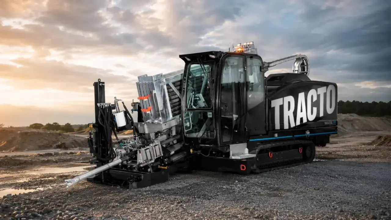
We carry out directional drilling with our own GRUNDODRILL 15 XPT rig made by Tracto Technik. On projects confirmed by reference letters we have completed about 1.5 km of directional drilling and pipe jacking in total: about 600 m on the 15 kV line undergrounding in Toruń, about 550 m (including SRS Ø160 pipe jacking) on the MV/LV network rebuild in 8 villages and about 350 m on the supply lines for RS Maliniec in Konin.
The rig, a mini excavator for launch and reception pits, and a lorry with an HDS crane for transporting ducts and equipment form a set that lets us drill without bringing in outside firms — which makes planning and coordination with other works along the route easier.
We drill both as part of our own cable line contracts and as a service for other contractors — for power networks and fibre-optic ducts. Details are on our horizontal directional drilling page.
See also
Read next
Horizontal directional drilling
Horizontal directional drilling and pipe jacking under roads, railways and rivers — ducts for MV, LV and fibre cables. Own Tracto-Technik GRUNDODRILL rig.
Learn moreFrom design to acceptance — building a line
Stages of building an MV cable line: design and approvals, site preparation, trenching and drilling, cable laying, accessories, testing and handover.
Learn moreMV/LV network rebuild — 8 villages
MV/LV network rebuild in 8 villages for PIWOWARSKI: 5,606 m of 3×NA2XS(F)2Y 1×150/25 mm² cable, ~550 m of drilling and pipe jacking. PLN 486,120 net.
Learn moreNeed a crossing under a road or watercourse?
We carry out directional drilling with duct pullback — as part of a cable line contract or as a standalone service. Send us the location and lengths.