
Knowledge · Substations
Inside an MV/LV transformer substation
An unassuming concrete kiosk or a transformer on a pole is the last link between the medium-voltage network and the socket at home. Let's look inside.
Electricity travels through the medium-voltage network — usually at 15 or 20 kV — from the GPZ primary substation to villages, towns and businesses. Customers in homes, farms and small firms, however, need 400/230 V. The change of voltage level is provided by an MV/LV transformer substation. We explain the types of substation, what they consist of and how they are built.
The role of an MV/LV substation in the distribution network
An MV/LV transformer substation has three basic tasks:
- transforming voltage from medium (e.g. 15 or 20 kV) to low (0.4 kV);
- distributing energy into several low-voltage circuits supplying customers in the area;
- switching and protection — allowing the transformer or circuits to be disconnected, protecting them from short circuits and overloads and, in substations with several line bays, allowing supply to be switched on the MV side.
There are tens of thousands of such substations in the distribution network. In towns they are mostly indoor and packaged substations; in rural areas there are still a great many pole-mounted ones.
A substation's location is not arbitrary. The designer tries to place it as close as possible to the “centre of gravity” of the load, where most customers are concentrated. The shorter the low-voltage circuits, the lower the voltage drop and energy losses, and the better the supply quality for customers at the ends of the circuits. That is why, as development grows, operators often add new substations rather than extending existing LV circuits.
Types of substation: pole-mounted, packaged, indoor
| Type | Characteristics | Typical use |
|---|---|---|
| Pole-mounted | transformer mounted on a pole structure, fed from an overhead line, LV switchboard in a cabinet on the pole or at its base | rural areas, lower ratings and small groups of customers |
| Packaged (kiosk / compact) | prefabricated concrete or metal enclosure housing MV switchgear, transformer and LV switchboard; operated from outside or from an internal corridor | cable networks, housing estates, businesses, solar farms, undergrounded rural areas |
| Indoor (in a building) | equipment installed in a masonry building or a dedicated room within another building | town centres, large buildings, industrial plants |
Packaged substations dominate new cable networks. They arrive on site as finished, factory-tested modules, which shortens installation time and helps maintain consistent quality.
The choice of substation type depends on several factors: how it is fed (overhead or cable), the required rating and number of LV circuits, available land, the operator's requirements for future expansion, and access for operating staff and for possible transformer replacement. Operators usually have their own standards defining approved substation types and equipment.
How a pole-mounted substation is built
A pole-mounted substation is the simplest type of MV/LV substation. The pole or pole assembly carries:
- an overhead disconnector or switch-disconnector — for isolating the substation from the MV line, for example during works;
- MV fuses — protecting the network from the effects of a transformer fault;
- surge arresters — protecting the transformer from lightning overvoltages;
- the transformer — usually oil-immersed, outdoor type;
- the LV switchboard — a cabinet with protection for the low-voltage circuits running to customers.
The advantages of a pole-mounted substation are low cost and a small footprint; the disadvantages are limited rating, exposure to weather and dependence on an overhead line. That is why, when an MV line is undergrounded, pole-mounted substations are often removed and replaced with packaged ones.
Work on a pole-mounted substation requires the line or branch feeding it to be switched off and is carried out under the operator's procedures, including preparation of the workplace by authorised persons. Mounting the transformer on the structure also requires suitable lifting equipment.
Inside a packaged substation
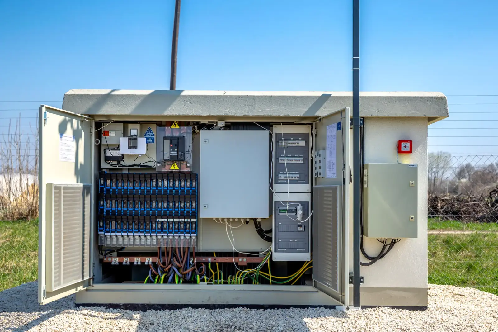
A typical packaged substation has three compartments or zones:
- The MV compartment with medium-voltage switchgear, to which MV cables are connected via terminations (often separable connectors).
- The transformer chamber with the MV/LV transformer and an oil containment bund.
- The LV compartment with the low-voltage switchboard, from which cables run to customers or cable junction boxes.
The enclosure stands on a foundation or a prefabricated underground section containing a cable space, into which cables enter through sealed glands. The enclosure provides natural ventilation for the transformer chamber, protection against water and unauthorised access, and carries warning signs.
Substations differ in how they are operated. In externally operated substations, doors open directly onto each compartment and operation is carried out from ground level. Substations with an operating corridor are larger but allow switching to be done under cover, whatever the weather. The choice depends on the operator's standards, available space and the expected rating.
MV switchgear — line and transformer bays
MV switchgear is made up of bays, each with a specific job:
- line bays — the MV line cables connect to these; two line bays allow the substation to be looped into the line so it can be fed from either direction;
- the transformer bay — feeds the transformer, usually through a switch-disconnector with MV fuses;
- metering or branch bays — depending on the substation's function, for example in substations connecting customers or renewable generators.
Modern substations are usually fitted with compact gas- or air-insulated switchgear with earthing switches and interlocks for safe operation. In networks where the operator uses automation, line bays may have motor operators and remote control via telecontrol, as well as fault passage indicators that help locate faults.
The MV/LV transformer
The heart of the substation is the transformer, which steps the voltage down from MV to 0.4 kV. Distribution networks are dominated by hermetically sealed oil-immersed transformers — the oil insulates and cools, and the sealed tank limits the oil's contact with air. In some applications, such as inside buildings, dry-type transformers with resin-encapsulated windings are used.
The transformer rating is matched to customer demand and the area's development prospects — smaller units in pole-mounted substations, larger ones in packaged substations. An oil containment bund is installed under oil-immersed transformers to protect the ground in case of a leak.
The transformer has an off-load tap changer that allows the ratio to be adapted to voltage conditions at that point in the network — the setting is chosen when the substation is commissioned, in line with the operator's guidance.
A transformer runs unattended but needs periodic inspection by the operator: checks of the tank and bushings, the oil (in units where this is possible), connections and cooling conditions. Substation design allows for replacing the transformer with a larger unit if demand grows — so the chamber and doors must be suitably sized and vehicle access must be provided.
LV switchboard, metering and earthing
The low-voltage switchboard distributes energy from the transformer into outgoing circuits. It most often uses fuse switch-disconnectors (for example strip-type) with fuse links matched to the cable sizes and loads. The switchboard may also include:
- energy metering or balance metering, if the operator requires it;
- auxiliary supply for the substation (lighting, service socket);
- LV surge arresters.
Every substation has an earthing system — electrodes driven into the ground or laid in a trench around the substation, connected to the structure, the transformer neutral and the cable screens as designed. Earth resistance is measured before the substation goes into service, and the result must meet the design and operator's requirements.
On the LV side, a substation usually supplies several cable or overhead circuits running to ZK cable junction boxes at properties or to distribution cabinets further into the network. In cable networks, junction boxes act as branching points and as the ownership boundary between the operator's network and the customer's installation.
How a packaged substation is built
A new packaged substation is typically built in this order:
- Site preparation — setting-out survey, excavation for the foundation or underground section, sub-base.
- Earthing — laying earth electrodes and conductors before the substation is placed.
- Placement — setting the prefabricated underground section and enclosure with a crane or a lorry-mounted HDS crane.
- Equipment installation — if the transformer is delivered separately, placing it in the chamber; connecting the switchgear.
- Cable entry — MV and LV cables are brought in through the glands, terminations are installed and connected to the switchgear bays.
- Testing — earthing and insulation resistance measurements, checks of switchgear and interlocks, cable line tests.
- Commissioning — after acceptance by the operator, the substation is energised and customers are switched over.
Logistics are important. The concrete enclosure and the transformer are heavy items delivered by specialist transport and set in place by crane — so access, room for the crane and a safe working zone must be ensured. Before placement, the level and bearing capacity of the ground are checked, as they determine correct positioning of the substation and the tightness of the cable glands.
In network rebuilds, building new substations goes hand in hand with removing old pole-mounted ones that are no longer needed.
MV/LV substations on our projects
On the contract for ENEA Operator in Niegosławice municipality, which we delivered as consortium leader, the scope included installing and building three sets of new MV/LV transformer substations while dismantling three pole-mounted transformer substations. The same contract included an MV cable line of 1×150/25 mm² with a length of 3 × 5,715 m, LV cable lines and cable junction boxes, and the removal of 8.266 km of 20 kV MV overhead line — a typical example of a rebuild in which the entire supply arrangement of an area changes.
We build MV/LV transformer substations and cable junction boxes for operators, contractors and investors, including as part of renewable grid connections. We can also take on equipment supply. Find out more on our MV/LV substations page.
See also
Read next
MV/LV substations
Construction of MV/LV transformer substations, ZKSN and LV cable junctions, replacement of pole-mounted units, MV and LV cable connections and testing.
Learn moreENEA Operator — MV 20 kV network, Niegosławice
BIGBUD as consortium leader for ENEA Operator: 3 MV/LV substations, MV cable line 3 × 5,715 m, 8.266 km of MV overhead line removed. PLN 2.4m net.
Learn moreConnecting a solar farm to the MV grid
How to connect a PV farm to the MV grid in Poland: connection conditions, the DSO agreement, design, construction of the connection, acceptance and start-up.
Learn moreNeed a contractor for an MV/LV substation?
We place the substation, build the MV supply and LV circuits, install the earthing and carry out the tests. Send us the design or a description of the scope.